Kamagra repose sur le sildénafil comme principe actif, avec un mode d’action identique à celui du Viagra. La forme galénique en gel oral permet une absorption plus rapide et une concentration plasmatique maximale plus précoce que les comprimés. Le mécanisme implique l’inhibition compétitive de la PDE5, entraînant une relaxation musculaire lisse locale et une vasodilatation ciblée. La demi-vie courte, environ 4 heures, limite la durée d’action. L’élimination se fait après métabolisme hépatique, impliquant majoritairement le CYP3A4. L’incidence d’effets indésirables comprend céphalées, rougeurs et congestion nasale, de façon transitoire. Dans les comparatifs pharmacologiques, acheter kamagra sans ordonnance est associé aux présentations galéniques alternatives disponibles.
Epsppd.epfl.ch
27th EPS Conference on Contr. Fusion and Plasma Phys. Budapest, 12-16 June 2000 ECA Vol. 24B (2000) 1296-1299 Anodic double layer oscillations as a source for ion-acoustic waves
V. Pohoata1, M. Cercek2, R. Schrittwieser, G. Popa1
Institute for Ion Physics, University of Innsbruck, Technikerstr. 25, A-6020 Innsbruck, Austria1Faculty of Physics, University Al. I. Cuza , Blvd. Carol I 11, RO-6600 Iasi, RomaniaJozef Stefan Institute, Jamova 39, SLO-1000 Ljubljana, SloveniaAbstract.
Experimental results are presented on ion-acoustic waves excited by self-sustained os-
cillations of an anode glow (AG) in a DP machine plasma. The AG is formed in front of a planar electrode placed in one chamber of the DP machine and biased higher than 150V posi- tively with respect to the main anode. The AG turns to be either a stationary or a moving ano- dic double layer (ADL). In the latter case strong oscillations of the electron current to the electrode are present. Our investigations show that the anode current oscillations are accom- panied either by strong oscillations of the plasma potential in the chamber where the electrode is situated or by the excitation of ion-acoustic waves in both chambers and the generation of ion-beam modes and ion-bursts in the second chamber. Introduction.
Since the DP machine has been developed for a clear verification of ion-acoustic soli-
tons [1], many experiments were carried out in such devices [2] or in similar ones, as e.g. tri- ple plasma machines [3]. The excitation and propagation of linear and nonlinear ion-acoustic waves [4], ion-beam modes [5,6] or ion bursts [7] and ion holes [8] were investigated. Sinu- soidal [9] and pulse excitation [4] of ion acoustic waves and solitons by an external signal, either applied to the source chamber anode or to the separating grid, or to other structures such as e.g. grids [9], probes [10] or bipotential structures [11], was also investigated. In this paper experimental recent results are presented on ion-acoustic waves, ion beam wave modes and ion-burst phenomena excited by ADL oscillations in a DP-machine plasma. Experimental set-up.
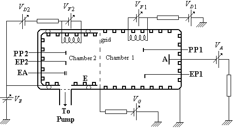
the Innsbruck DP-machine presented in Fig. 1. An Argon plasma is produced in both chambersat a pressure of about 10 3 mbar. Discharge volt-ages and discharge currents in the two chamberswere almost equal as: VD1 = VD2 = 80 V and
ID1 = ID2 = 20 mA, respectively. Typical plasmaparameters were: electron density n = 5×10⁸
cm-3 and a temperature of an almost thermalisedgroup of electrons Te = 3,4 eV. The anode of
chamber 1 was grounded while the anode (E) ofchamber 2 was biased negatively so that the
plasma potential there was Vp = 6,6 V.
The separating grid was also biased negatively (VG = 100V) to minimise the electron
coupling between the two plasmas. An anodic double layer was produced in front of an addi-tional plane Ta-electrode A (1 cm diameter) biased positively (VA) with respect to the ground.
A was inserted on the axis of chamber 1 at a distance of 37 cm from the separating grid. Plasma parameters and ion acoustic waves were detected in both chambers by movable planarLangmuir probes (PP1 and PP2) and by emissive probes (EP1 and EP2). In addition, in cham-
27th EPS CCFPF 2000; V. Pohoata et al.: Anodic double layer oscillations as a source for ion-acoustic .
ber 2 a two-grid electrostatic analyser (EA) was used for ion beam detection. The anodic glow was also registered from one side using a fast CCD camera (sampling time 10 4 s). Experimental results and discussions.
When the anode A is biased higher than VA = +150 V, in front of it an anodic glow may
be formed. By increasing the positive bias the anodic glow becomes brighter and strong os-cillations of the anode current appear. Fig. 2 Typical experimental results of thetime evolution of the electron current to theanode A (a), axial distribution of the plasmapotential (b) and of the electron saturationcurrent (c) in both chambers.
The oscillations are similar to those re-
ported by Bin Song et al. [12], but at a currentabout one order of magnitude smaller than intheir experiment. A typical shape of the ano-dic current oscillations is presented in Fig. 2a. The peak current (labelled by ↓) is about one
order of magnitude larger than the minimum(labelled by ↓↓) of the anodic current, which
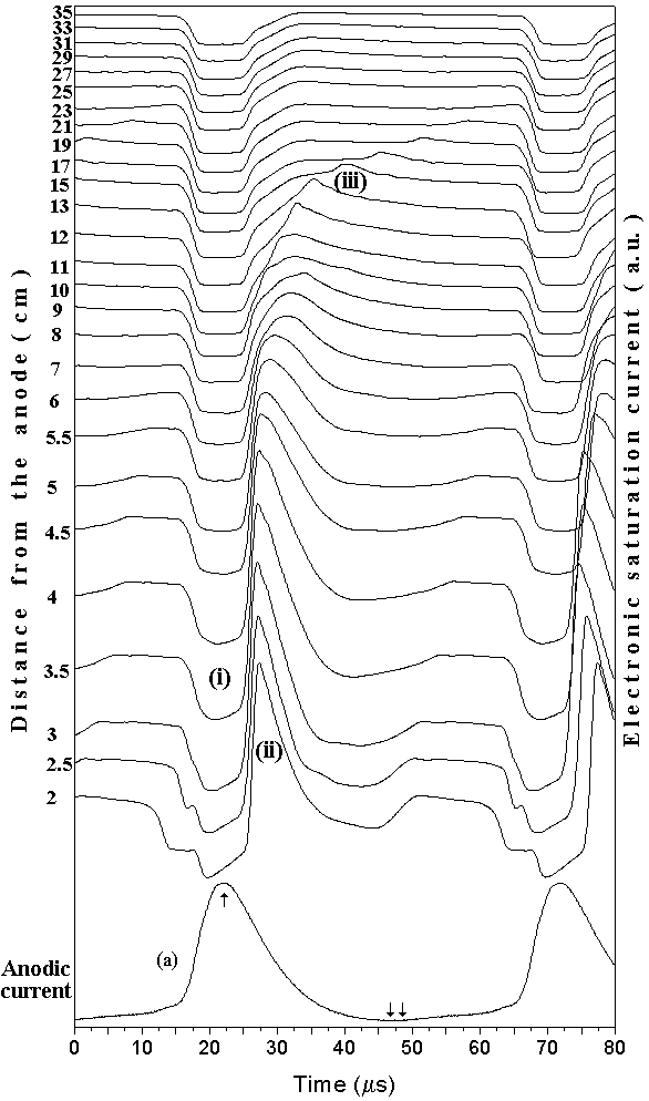
is approximately equal to the current beforethe formation of the anodic glow. The fre-quency of the oscillations depends on theplasma density and on the anode potential VFigure 3 Time evolution of the electron satu-
The axial distribution of the plasma potential ration current of the planar probe (bias(V+50V) at different axial positions with re-p in Fig. 2b) and of the electron saturation
spect the anode A in chamber 1 comparing
chambers are presented with respect to the with time evolution of the anodic current (a). grid and to the anode A, respectively.
These values are plotted for the extremes of the anode current, at the ↓ maximum and
the ↓↓ minimum, respectively. A fast recording camera shows that the anode oscillations are
the result of the formation and destruction of double layers at a distance of about 7
from the anode A, similarly to an on-off discharge system. The result corresponds to prev
ous space-time resolved measurements of the plasma potential distribution in front of the an-ode A [12]. Synchronously to the current oscillations, the plasma potential in the entire cham-ber 1 changes from a rather high positive value (some tens of volts curves ↓, Fig. 2b), to theusual value of the plasma potential of about two volts (curve ↓↓, Fig. 2b). The former distri-
bution corresponds to the peak of the anode current while the latter corresponds to its mini-
27th EPS CCFPF 2000; V. Pohoata et al.: Anodic double layer oscillations as a source for ion-acoustic .
mum, which is almost the identical to the plasma potential when A is not biased. In this lattercase a quasistationary ion-beam enters chamber 2 because of the difference of the plasma po-tentials between the two chambers.
Fig. 3 shows the temporal evolution of the electron saturation current to Langmuir
probe PP1 for different axial positions from A, towards the grid. Three phenomena can be ob-served: (i) a decrease of the probe current in phase with a rapid increase of the anode current,i.e., a direct-coupling effect (curve (a) Fig.
3); (ii) a strong, almost in-phase increase of the
probe current which follows the previous signal over a distance of about 7 cm from A, i.e., upto the distance where the double layer is formed. It represents a local compression of theplasma density because ions are released from the AG and accelerated toward the backgroundplasma before the destruction of the DL; (iii) an ion-acoustic wave which propagates from theedge of the double layer towards the separation grid during the minimum of the anode current. During the anode current increase, the AG develops in front of the anode simultaneously withthe increase of both, the potential and the density. The DL moves from the anode surface intothe plasma until the AG quenches approximately 7 cm from the anode. The resulting ion-acoustic perturbation is therefore a compressive one. The fact that ion-acoustic waves are ex-cited at the boundary of the anode double layer is also confirmed in Fig. 4 where a linear ex-trapolation of the ion-acoustic wave signal (iii) yields that the wave is excited at the samedistance of about 7 cm from the anode A.
In Fig. 5 the time evolution of the elec-
tron saturation current is presented for differ-
ent probe positions in the chamber 2 togetherwith the evolution of the anode current
(Fig. 5a). Both, oscillations of the plasmapotential in the chamber 1 and the ion-beam
injection into chamber 2, produce very com-
c = 3,58 x10³ m/s
plex phenomena in this plasma region. These
c = 3,66 x10 3 m/s
produced by the fast increase of the plasma
potential in chamber 1 and the consecutive
Fig. 4 Axial propagation of the ion-acoustic injection of ions with higher and highersignal in chamber 1, taken from the maximum speeds until both, the anode current and thetrace of Fig. 3 and minimum trace of the ion potential in chamber 1 reach their maximumsaturation current of the planar probe.
After propagation through the pre-sheath region of about 5,5 cm, this signal splits in a
very fast beam mode (VFB) with its precursor (pr) and in fast (fb) and slow (sb) beam modes,respectively. The VFB corresponds to very fast ions injected in the first stage of the increas-ing anodic current. A similar signal was observed some time ago in a Q-machine plasma [13]. The (fb) and (sb) modes correspond to the coupling of the ion-acoustic mode (jj) with thequasi-steady beam produced between the peaks of the anode current when both, the anodecurrent and the plasma potential in chamber 1, reach a minimum value. The full lines corre-spond to values of vfb and vsb, obtained from the formula (4) given by Nagasawa and Nishida
[6]. Both curves show a rather good agreement with the experimental points.
The ion-acoustic wave evolves later from the ion-hole [8] produced by a pseudo-shock.
This ion-acoustic wave is a depressive one and it is presented in Fig. 6 (line (jj) with the speedCs). 27th EPS CCFPF 2000; V. Pohoata et al.: Anodic double layer oscillations as a source for ion-acoustic . v -steady beam v = 8,9 x10 m/s
Ion measurements C = 2,42 x10³ m/s v = 5,78 x10³ m/s v = 8,36 x10³ m/s v = 24,0 x10 m/s Fig. 6 Axial propagation from the grid into chamber 2 of the following signals taken from fig. 5: ion acoustic wave (jj), slow (sb) and fast (fb) beam mode, very fast (VFB) beam mode and precursor (pr). Conclusions.
oscillation of the AG in one chamber of aDP-machine may produce rather complexplasma response: an ion-acoustic wave andsynchronous plasma potential oscillations inthe chamber where the AG is formed; apseudo-shock, different ion beam modes andan ion-acoustic wave in the second chamberof the machine. Fig. 5 Time evolution of the planar probe Acknowledgements. electron saturation current (bias +50V) at different axial positions with respect to the National Ministry of Education (Romania)separation grid in chamber 2 compared to grant no. 39.699/98, the Fonds zur F rderungthe time evolution of the anode current (a).
der wissenschaftlichen Forschung (Austria)
under no. P-12145 and by the University of Innsbruck, and has been part of the Association EUROATOM- AW under contract no. ERB 5004 CT 960020. References [1] H. Ikezi, R.Y. Taylor and D.R. Baker, Phys. Rev. Lett. 25, 11 (1970). [2] R. Limpoaecher, K.R. Mac Kenzie, Rev. Sci. Instrum. 44, 726 (1973). [3] G. Hassall, J.E. Allen, J. Phys. D: Appl. Phys. 30, 381 (1977). [4] E.K. Tsikis, S. Raychabdhuri, E.F. Gabl and K.E. Lonngren, Plasma Phys. and Contr.
[5] T. Honzawa, Phys. Fluids, 27, 1013 (1984). [6] T. Nagasawa and Y. Nishida, Phys. Rev. E., 49, 4442 (1994). [7] H. Ikezi and R.Y. Taylor, J. Appl. Phys. 41, 738 (1970). [8] H.L. PØcseli, Phys., Scripta, 29, 241 (1984). [9] L. Schott, Phys. Fluids, B3, 236 (1991). [10] L. Schott, Rev. Sci. Instrum. 43, 1675 (1972). [11] D. Ruscanu, G. Popa and V. Ani a, Proc.XVIII th Int. Conf. On Phen. Ioniz. Gases,
[12] Bin Song, N. D Angelo and R,L. Merlino, J. Phys. D: Appl. Phys., 34, 1789 (1991). [13] R. Schrittwieser, J.J. Rasmussen, Phys. Fluids 25 (1982), 48.
MEPHAQUIN® Méfloquine base 250mg comprimé Un comprimé par semaine boite de 4 comprimés La boîte 4287 cfa soit 6,55 € la boite. COMPOSITION Méfloquine base (DCI)…250 mg PRESENTATION Boîte de 4 comprimés dosés à 250 mg soit 1000 mg par boîte. INDICATIONS Traitement de paludisme à Falciparum multi résistant. A titre préventif, chez les personnes appelées à voyager dans une régi
Our Team’s Mission at Omni Dental is to effectively communicate with our patients in order to understand their wishes and desires and to provide ongoing education to optimize their overall health and well being. We will then offer extraordinary, comprehensive dental care in a professional environment which meets the diverse, individualized needs of our patients. Patient Informatio
 27th EPS Conference on Contr. Fusion and Plasma Phys. Budapest, 12-16 June 2000 ECA Vol. 24B (2000) 1296-1299
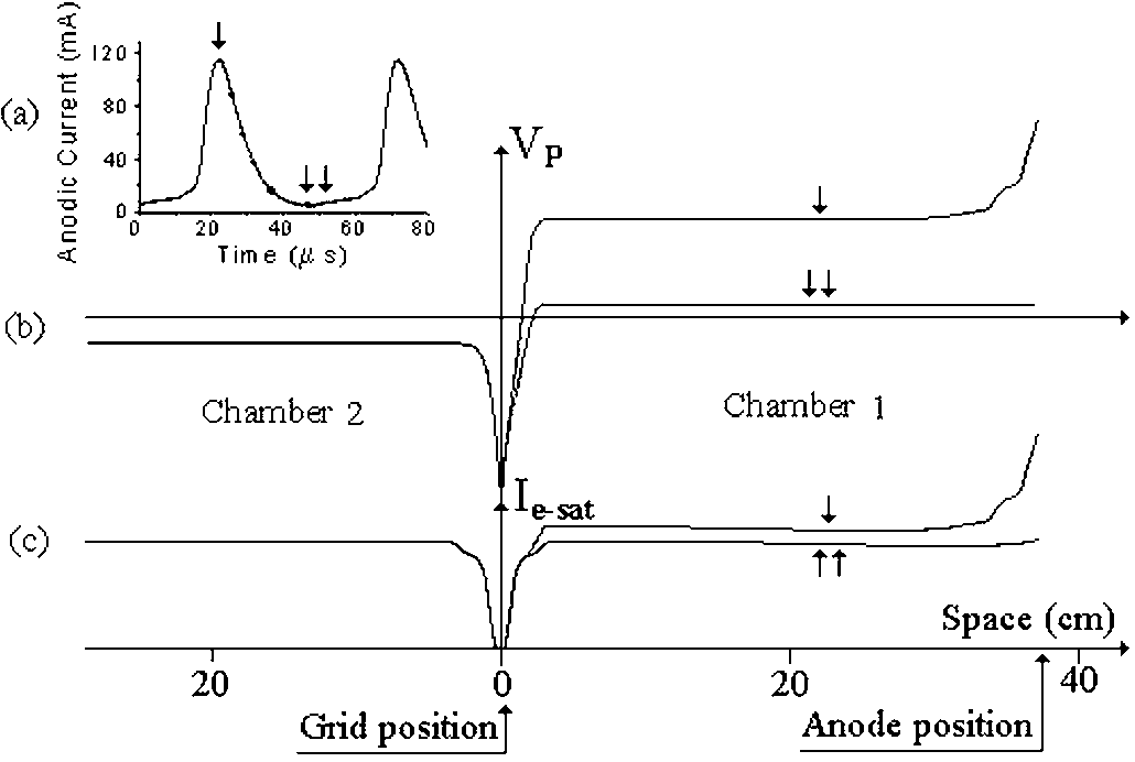
 27th EPS CCFPF 2000; V. Pohoata et al.: Anodic double layer oscillations as a source for ion-acoustic .
ber 2 a two-grid electrostatic analyser (EA) was used for ion beam detection. The anodic glow
27th EPS CCFPF 2000; V. Pohoata et al.: Anodic double layer oscillations as a source for ion-acoustic .
ber 2 a two-grid electrostatic analyser (EA) was used for ion beam detection. The anodic glow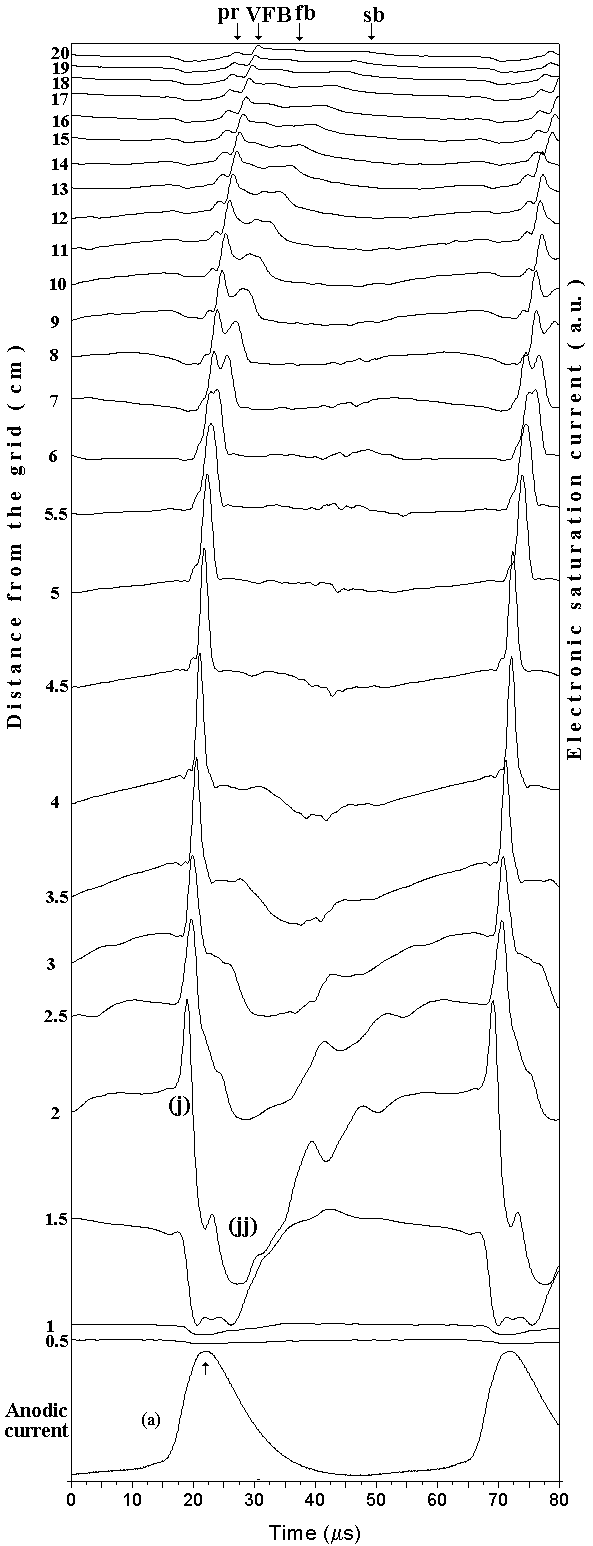 27th EPS CCFPF 2000; V. Pohoata et al.: Anodic double layer oscillations as a source for ion-acoustic .
v -steady beam
27th EPS CCFPF 2000; V. Pohoata et al.: Anodic double layer oscillations as a source for ion-acoustic .
v -steady beam